Fooling Around with Foveated Rendering
Shadertoy is a wonderful tool which lets users create and share a type of program called a fragment shader online. The true magic of shadertoy is its community of very talented graphics programmers who build incredible works of art despite having access to only a sliver of the traditional graphics pipeline.
Some of these shaders are very computationally intensive and even in a small window, they crawl along well below their intended 60 frames per second on my old laptop. Inspired by a technique in the VR community called Foveated Rendering, I decided to try to optimize these shaders by only rendering a fully detailed image within a small focal region. As you move away from the focal point the image quality decreases.
This rendering scheme is motivated by biology. It turns out your eye notices more detail in the center of your vision than in the periphery. Some VR graphics programmers realized they could take advantage of this phenomenon to increase the effective resolution of images by increasing image quality towards the center of your vision. An in depth discussion of foveated rendering can be found in the “previous work section” of this paper.
I did not have the time, equipment or the background necessary to implement a full foveated rendering system but it was fun to fool around with the concept.
Before diving into the technical details let’s look at a simple shadertoy fragment shader.
void mainImage(out vec4 fragColor, in vec2 fragCoord)

{
}
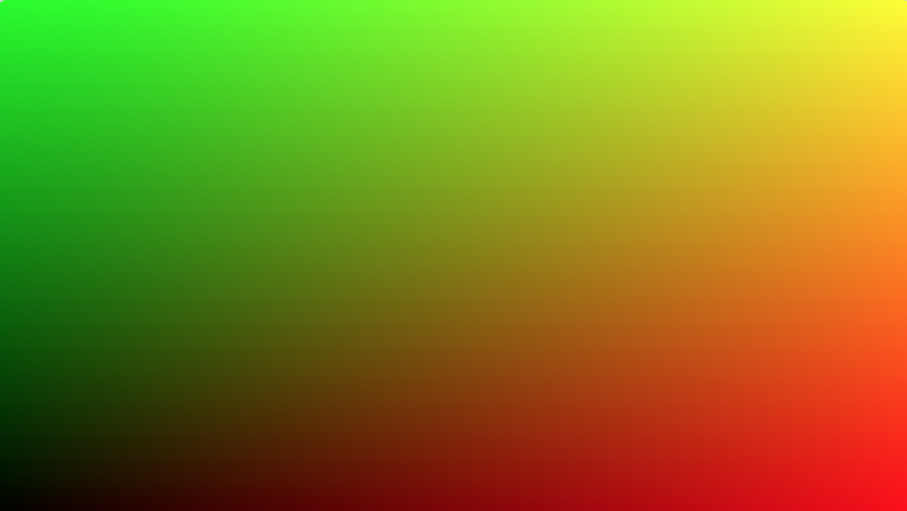
This program runs once for each pixel on the screen. Each time it runs, we receive the input variable fragCoord. fragCoord is a 2d vector which contains the x and y coordinates of the pixel being drawn. We normalize those coordinates by dividing by iResolution, another 2d vector, which contains the width and height of the image. Finally we output a color to the screen, whose red and green channels are proportional to the x and y position of the pixel being drawn. The output of this shader looks like this:
Side note, why do these shader programs require their own language? Shaders are special because they run on the graphics card instead of the cpu. They are highly parallel. A helpful mental model might be imagining that each pixel is colored simultaneously. Therefore a lot of things that we take for granted in normal program languages such as liberally accessing memory and branching become much more difficult.
In shadertoy shaders the bottleneck is always in the pixel rendering step. So to speed them up we want to only render a subset of the all the pixels on the screen. It seems like selectively rendering pixels should be as simple as adding a branch to the per pixel shader code that looks like:
void mainImage(out vec4 fragColor, in vec2 fragCoord)

{
}
Unfortunately we cannot just use an if statement inside of the shader to save us from rendering all the pixels. Unlike normal programming languages, fragment shaders always execute both parts of each branch due to gpu limitations. So while our above code will still have to spend the sample amount of time evaluating compuationally intensive work.
Luckily, it turns out that graphics drivers can selectively mark which pixels not to shade by writing their location to a special buffer called the stencil buffer. We can use this stencil buffer to only shade the subset of pixels we are interested in.
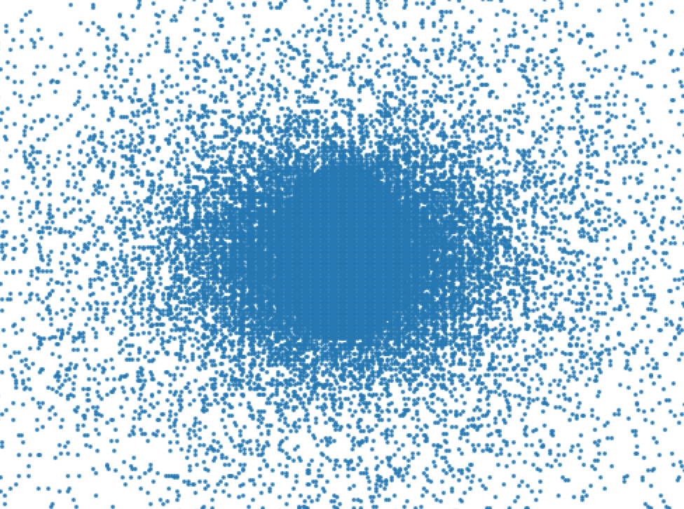
Once I could efficiently render a subset of the pixels, I needed to come up with a pre-generated sampling pattern. Most foveated rendering techniques seem to use a grid, but I decided to try a non uniform approach. Searching for some kind of optimal sampling pattern seemed like an interesting problem and if I was going to devote more time to this I'd explore options like blue noise. However in the interest of time, I just decided fill in a small circle in the center and then use samples drawn from one low variance and one high variance gaussians centered at the middle of the screen to place the rest of the pixels. The final sampling pattern ended up looking like this:
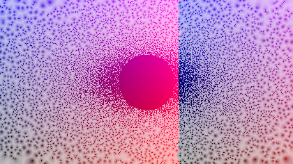
Next, I needed a way to fill in all the missing pixels in the final image. The approach I took was pretty simple. I started by mapping each pixel in the final screen to its nearest neighbor. Since my sampling pattern was predetermined, I could create this map beforehand and pass it into the shader as a texture. Here's what this mapping looks like:
And here’s a gif of the mapping applied to a shadertoy created by the extremely talented Inigo Quilez:
The above screen is 420x236 pixels and only 1/10th of those pixels are actually rendered. The focal point is directly in the center of the screen. Here's what the full resolution version looks like:
And here's what it looks like with only our sampling pixels:
![]()
One little improvement I tried was to make 4 different maps. The kth map mapped each pixel in the final image to its kth nearest sampled neighbor. I weighted each of neighbors by the inverse of their distance to the pixel in question. I actually even tried using some gradient descent based optimization to fine tune the weights but ended up seeing little improvement. It also seemed that increasing the number of maps beyond 4 did not improve things much either. Here's what the example from above looks like with weighted interpolation between the four closest neighbors of each pixel (we are still rendering only 1/10th of the total pixels):

Finally, here's the shader with 1/5th of the total pixels rendered (as opposed to 1/10th shown above):
![]()
Okay that's all cool but does this technique actually increase performance? I did not do a rigerous benchmark, but this shader goes from around 20-25 fps on my plugged in laptop to 60 fps when reduced to 1/5th of the total pixels. Another shader went from around 15 fps to 60 fps.
One last side note is that this method can be used with any 3d scene and is not exclusive to shader toys. I just chose to use them because they are always bottlenecked by the pixel rendering step and they are really pretty!
Further questions:
- How do we achive better temporal stability? (the paper I mentioned earlier talks about this)
- Can we dynamically change the sampling pattern to give us better results? For example what if we sampled along edges or areas where large amounts of motion is occuring? Of course to do this we would need to compute our nearest neighbor mappings on the fly (there are actually some shadertoys which already demonstrate capability).
- How could this scheme improve if we had access to the internals of the 3d scene? For example, could we adjust our sampling pattern based on depth information?
- How does this actually look in VR?
Have questions / comments / corrections?
Get in touch: pstefek.dev@gmail.com
Discussion on Hacker News